
I’m mostly a software guy. Except for chemistry and blowing stuff up, I’ve not tinkered much with hardware. But I’ve been fascinated by it, and especially with electronics. So far it’s been contained to electronics modding on HP calculators. I decided I need a tool that can teach me electronics properly from the ground up.
circuit is an electronics bench in the terminal. Put batteries, resistors, capacitors, LEDs, switches and transistors on a grid. Wire them up. Press p. Every voltage and every current is worked out while you watch.
Light an LED
Challenges teach one idea at a time, from lighting an LED to building a stopwatch. Each one is conqured when your circuit works.
The first one: light an LED. It needs about 2 volts. The battery gives 9. A 470 Ω resistor in the loop holds the current down. Then take the resistor out…
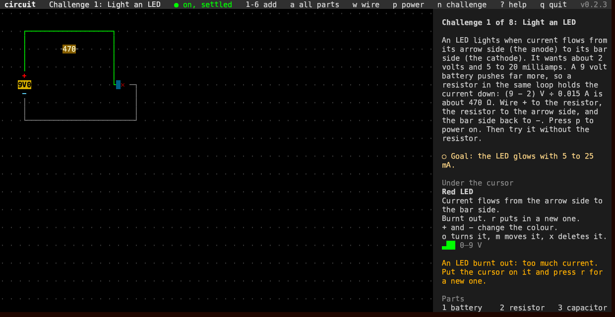
r puts in a new one.
Make it blink
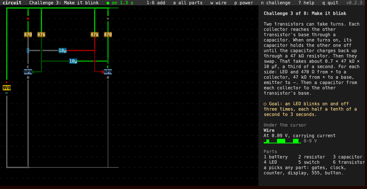
Two transistors and two capacitors take turns. One LED is on for a third of a second, then the other. That’s the circuit at the top.
Wires glow green with voltage. Look at the lit LED: the wire after it is gray. I asked Claude why. The LED and its resistor use up the 9 volts, so that wire sits near zero. But the same current flows all the way around the loop.
So a wire carrying current turns to double lines. The whole loop shows, from + and back to −.
Logic
a opens every part: gates, a clock, a counter, a digit display, the 555 timer, a push button.
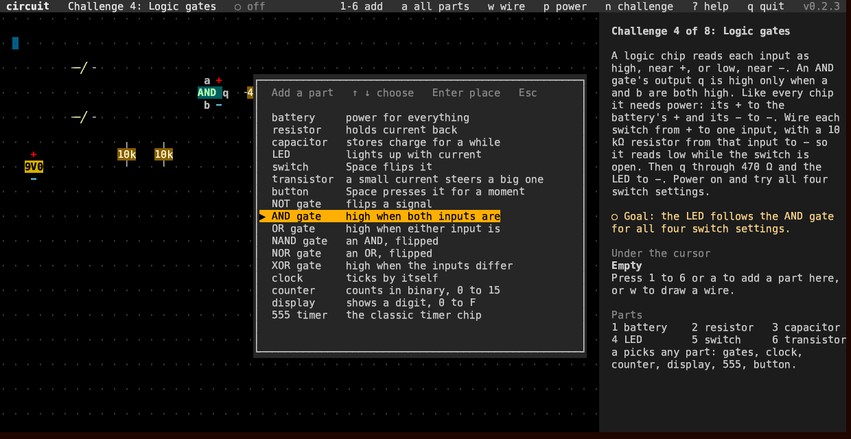
Every chip needs its + and − wired to the battery. Like the real thing.
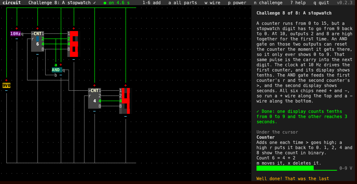
The last challenge is a stopwatch. A counter counts to 15, but a stopwatch digit goes from 9 back to 0. At 10, its outputs 2 and 8 are high together for the first time. An AND gate on those two resets the counter… and the same pulse counts the seconds on the next one.
Details
The panel on the right shows what the cursor is on, down to the pin. And what it’s doing: the volts across, the current through, the power a resistor turns into heat.
Parts are marked like real ones. 4k7 is 4.7 kΩ, 10µ is 10 µF. And like real parts, none is exactly its value. Each is off by up to 1%.
Under the hood, the voltage at every junction is unknown. The currents into a junction add up to zero. That gives one equation per junction, all solved together, every simulated millisecond.
Summary
Built with Claude. One binary. No network. A circuit that has settled costs nothing.
Public Domain, like everything I make.
Link to this post: https://isene.org/2026/09/Circuits-In-The-Terminal.html